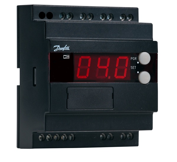
EKC 202
EKC Series • Refrigeration Controller
Quick Info
Output Functions
Refrigeration controller with defrost management
Technical Specifications
Display & Interface
| Display Type | LED |
| Display Digits | 4 |
| Buttons | 4 |
| LED Indicators | Compressor, Defrost, Fan, Alarm |
Power Supply
| Voltage | 230V AC |
| Voltage Range | 100-240V AC |
| Frequency | 50/60Hz |
| Power Consumption | 4VA |
Sensor Inputs
| Probe Inputs | 2 |
| Probe Type | NTC/PTC/PT1000 |
| Temp Range | -60 to 150°C |
| Accuracy | ±0.3°C |
Relay Outputs
| Relay Outputs | 3 |
| Relay Rating | 8A/250VAC |
Physical
| Panel Size | 71.5x28.5 mm |
| Depth | 60 mm |
| IP Rating | IP65 (front) |
| Weight | 110 g |
Operating Conditions
| Operating Temp | -25 to 55°C |
| Storage Temp | -40 to 70°C |
Wiring Terminals
| Terminal | Function | Type | Wire Color |
|---|---|---|---|
| L | Power L | Input |
brown
|
| N | Power N | Input |
blue
|
| S1+ | Air Sensor + | Input |
red
|
| S1- | Air Sensor - | Input |
white
|
| S2+ | Defrost Sensor + | Input |
red
|
| S2- | Defrost Sensor - | Input |
white
|
| DI | Digital Input | Input |
gray
|
| GND | DI Ground | Input |
gray
|
| K1 | Relay 1 (Comp) | Output |
black
|
| K2 | Relay 2 (Defrost) | Output |
orange
|
| K3 | Relay 3 (Fan) | Output |
green
|
| A | RS485 A | Comm |
blue
|
| B | RS485 B | Comm |
yellow
|
Important: Always disconnect power before wiring. Verify terminal numbers with the actual controller label before connecting.
Parameter Settings
| Code | Parameter | Range | Default | Description |
|---|---|---|---|---|
| r01 | Setpoint | -60 to 150 | 5 °C | Temperature setpoint |
| r02 | Differential | 0.1 to 20 | 2 °C | Switching differential |
| r04 | Min Setpoint | -60 to r01 | -30 °C | Minimum setpoint |
| r05 | Max Setpoint | r01 to 150 | 50 °C | Maximum setpoint |
| r12 | Air Calibration | -10 to 10 | 0 °C | Air sensor offset |
| r13 | Defrost Calibration | -10 to 10 | 0 °C | Defrost sensor offset |
| c01 | Compressor Delay | 0 to 30 | 0 min | Startup delay |
| c02 | Min Off Time | 0 to 30 | 0 min | Minimum compressor off |
| c03 | Min On Time | 0 to 30 | 0 min | Minimum compressor on |
| d01 | Defrost Type | 0=Off, 1=Elec, 2=Gas, 3=Cycle | 1 | Defrost method |
| d02 | Defrost Stop Temp | 0 to 25 | 6 °C | Termination temp |
| d03 | Max Defrost Time | 0 to 180 | 30 min | Maximum duration |
| d04 | Defrost Interval | 0 to 48 | 8 hr | Time between defrosts |
| d06 | Drip Time | 0 to 60 | 2 min | Drain time after defrost |
| d08 | Fan Delay | 0 to 60 | 0 min | Fan restart delay |
| F01 | Fan During Defrost | 0=Off, 1=On | 0 | Fan cutout control |
| A01 | High Temp Alarm | r01 to 150 | 15 °C | High alarm setpoint |
| A02 | Low Temp Alarm | -60 to r01 | -10 °C | Low alarm setpoint |
| A03 | Alarm Delay | 0 to 240 | 30 min | Alarm delay time |
Error Codes
Solution: Check S1 sensor wiring
Solution: Check S2 sensor wiring
Solution: Check all sensor connections
Solution: Reset parameters or replace
Solution: Check refrigeration system
Solution: Normal operation
Frequently Asked Questions
Press middle two buttons simultaneously for 3 seconds
Use d04 for interval hours, or configure d20-d27 for specific times
NTC, PTC 1000, and PT1000. Configure via o06 parameter
Alternative Models (Cross Reference)
Manufacturer Information
Brand: Danfoss
Country: Denmark